LESSON INTRODUCTION
Computer networks are complex systems that incorporate multiple functions, standards, and proprietary technologies. The Open Systems Interconnection (OSI) model is used to try to simplify some of this complexity. It divides network technologies between seven functional layers. This makes it easier to separate and focus on individual concepts and technologies while retaining an understanding of relationships to the functions of technologies placed in other layers.
Jaringan komputer adalah sistem kompleks yang menggabungkan beberapa fungsi, standar, dan teknologi eksklusif. Model Open Systems Interconnection (OSI) digunakan untuk mencoba menyederhanakan beberapa kompleksitas ini. Ini membagi teknologi jaringan antara tujuh lapisan fungsional. Ini membuatnya lebih mudah untuk memisahkan dan fokus pada konsep dan teknologi individu sambil mempertahankan pemahaman tentang hubungan dengan fungsi teknologi yang ditempatkan di lapisan lain.
This lesson uses the OSI model to give you an overview of the technologies that you will be studying in the rest of the course. You will compare the functions of these layers in the OSI model and apply those concepts to the installation and configuration of a small office/home office network.
Pelajaran ini menggunakan model OSI untuk memberi Anda gambaran umum tentang teknologi yang akan Anda pelajari di sisa kursus. Anda akan membandingkan fungsi lapisan ini dalam model OSI dan menerapkan konsep tersebut ke instalasi dan konfigurasi kantor kecil
LESSON OBJECTIVES
In this lesson, you will:
Compare and contrast OSI model layers.
Configure SOHO networks.
Compare and Contrast OSI Model Layers
Introduction: Compare and Contrast OSI Model Layers
Networks are built on common standards and models that describe how devices and protocols interconnect. In this topic, you will identify how the implementation and support of these systems refer to an important common reference model: the Open Systems Interconnection (OSI) model. The OSI model breaks the data communication process into discrete layers. Being able to identify the OSI layers and compare the functions of devices and protocols working at each layer will help you to implement and troubleshoot networks.
Open Systems Interconnection Model
A network is two or more computer systems that are linked by a transmission medium and share one or more protocols that enable them to exchange data. You can think of any network in terms of nodes and links. The nodes are devices that send, receive, and forward data and the links are the communications pathways between them.
The International Organization for Standardization (ISO) developed the Open Systems Interconnection (OSI) reference model ( iso.org/standard/20269.html) to promote understanding of how components in a network system work. It does this by separating the function of hardware and software components to seven discrete layers. Each layer performs a different group of tasks required for network communication.
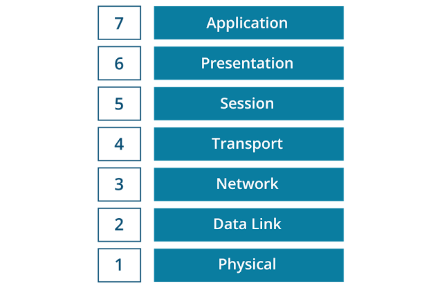
Although not all network systems implement layers using this precise structure, they all implement each task in some way. The OSI model is not a standard or a specification; it serves as a functional guideline for designing network protocols, software, and appliances and for troubleshooting networks.
Tips: To remember the seven layers, use the following mnemonic: All People Seem To Need Data Processing.
Data Encapsulation and Decapsulation
A network protocol is a set of rules for exchanging data in a structured format. A network protocol has two principal functions:
- Addressing-Describing where data messages should go. At each layer, there are different mechanisms for identifying nodes and rules for how they can send and receive messages.
- Encapsulation-Describing how data messages should be packaged for transmission. Encapsulation is like an envelope for a letter, with the distinction that each layer requires its own envelope. At each layer, the protocol adds fields in a header to whatever data (payload) it receives from an application or other protocol.
A network will involve the use of many different protocols operating at different layers of the OSI model. At each layer, for two nodes to communicate they must be running the same protocol. The protocol running at each layer communicates with its equivalent (or peer) layer on the other node. This communication between nodes at the same layer is described as a same layer interaction. To transmit or receive a communication, on each node, each layer provides services for the layer above and uses the services of the layer below. This is referred to as adjacent layer interaction.
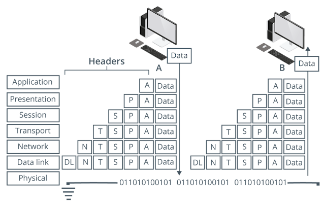
When a message is sent from one node to another, it travels down the stack of layers on the sending node, reaches the receiving node using the transmission media, and then passes up the stack on that node. At each level (except the physical layer), the sending node adds a header to the data payload, forming a “chunk” of data called a protocol data unit (PDU). This is the process of encapsulation.
For example, on the sending node, data is generated by an application, such as the HyperText Transfer Protocol (HTTP), which will include its own application header. At the transport layer, a Transport Control Protocol (TCP) header is added to this application data. At the network layer, the TCP segment is wrapped in an Internet Protocol (IP) header. The IP packet is encapsulated in an Ethernet frame at the data link layer, then the stream of bits making up the frame is transmitted over the network at the physical layer as a modulated electrical signal.
The receiving node performs the reverse process, referred to as decapsulation. It receives the stream of bits arriving at the physical layer and decodes an Ethernet frame. It extracts the IP packet from this frame and resolves the information in the IP header, then does the same for the TCP and application headers, eventually extracting the HTTP application data for processing by a software program, such as a web browser or web server.
Layer 1-Physical
The physical layer (PHY) of the OSI model (layer 1) is responsible for the transmission and receipt of the signals that represent bits of data from one node to another node. Different types of transmission media can be classified as cabled or wireless:
- Cabled-A physical signal conductor is provided between two nodes. Examples include cable types such as copper or fiber optic cable. Cabled media can also be described as bounded media.
- Wireless-Uses free space between nodes, such as microwave radio. Wireless media can also be described as unbounded media.
The Physical layer specifies the following:
- Physical topology-The layout of nodes and links as established by the transmission media. An area of a larger network is called a segment. A network is typically divided into segments to cope with the physical restrictions of the network media used, to improve performance, or to improve security. At the Physical layer, a segment is where all the nodes share access to the same media.
- Physical interface-Mechanical specifications for the network medium, such as cable specifications, the medium connector and pin-out details (the number and functions of the various pins in a network connector), or radio transceiver specifications.
- The process of transmitting and receiving signals over the network medium, including modulation schemes and timing/synchronization.
Devices that operate at the Physical layer include:
- Transceiver-The part of a network interface that sends and receives signals over the network media.
- Repeater-A device that amplifies an electronic signal to extend the maximum allowable distance for a media type.
- Hub-A multiport repeater, deployed as the central point of connection for nodes.
- Media converter-A device that converts one media signaling type to another.
- Modem-A device that performs some type of signal modulation and demodulation, such as sending digital data over an analog line.
Layer 2-Data Link
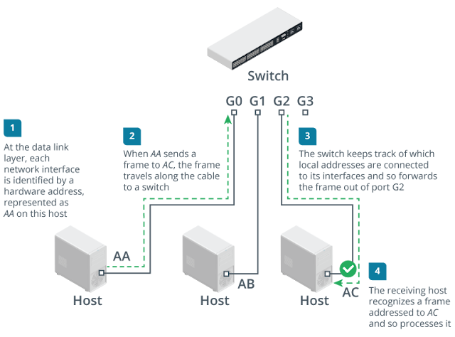
The data link layer (layer 2) is responsible for transferring data between nodes on the same logical segment. At the Data Link layer, a segment is one where all nodes can send traffic to one another using hardware addresses, regardless of whether they share access to the same media. A layer 2 segment might include multiple physical segments. This is referred to as a logical topology.
Relatively few networks are based on directly connecting hosts together. Rather than making hosts establish direct links with one another, each host is connected to a central node, such as a switch or a wireless access point. The central node provides a forwarding function, receiving the communication from one node and sending it to another. The addresses of interfaces within the same layer 2 segment are described as local addresses or hardware addresses.
Nodes that send and receive information are referred to as end systems or as host nodes. This type of node includes computers, laptops, servers, Voice over IP (VoIP) phones, smartphones, and printers. A node that provides only a forwarding function is referred to as an intermediate system or infrastructure node.
The data link layer organizes the stream of bits arriving from the physical layer into structured units called frames. Each frame contains a network layer packet as its payload. The data link layer adds control information to the payload in the form of header fields. These fields include source and destination hardware addresses, plus a basic error check to test if the frame was received intact.
Devices that operate at the data link layer include:
- Network adapter or network interface card (NICs)-An NIC joins an end system host to network media (cabling or wireless) and enables it to communicate over the network by assembling and disassembling frames.
- Bridge-A bridge is a type of intermediate system that joins physical network segments while minimizing the performance reduction of having more nodes on the same network. A bridge has multiple ports, each of which functions as a network interface.
- Switch-An advanced type of bridge with many ports. A switch creates links between large numbers of nodes more efficiently.
- Wireless access point (AP)-An AP allows nodes with wireless network cards to communicate and creates a bridge between wireless networks and wired ones.
Layer 3-Network
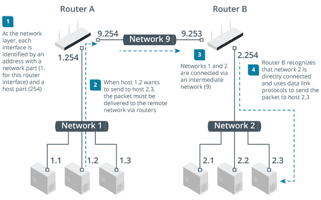
The network layer (layer 3) is responsible for moving data around a network of networks, known as an internetwork or the Internet. While the data link layer is capable of forwarding data by using hardware addresses within a single segment, the network layer moves information around an internetwork by using logical network and host IDs. The networks are often heterogeneous; that is, they use a variety of physical layer media and data link protocols. The main appliance working at layer 3 is the router.
The network layer forwards information between networks by examining the destination network-layer address or logical network address. The packet is forwarded, router by router (or hop by hop), through the internetwork to the target network. Once it has reached the destination network, the hardware address can be used to deliver the packet to the target node.
The general convention is to describe PDUs packaged at the network layer as packets or datagrams, and messages packaged at the data link layer as frames. Packet is often used to describe PDUs at any layer, however.
It is usually important for traffic passing between networks to be filtered. A basic firewall operates at layer 3 to enforce an access control list (ACL). A network ACL is a list of the addresses and types of traffic that are permitted or blocked.
Layer 4-Transport
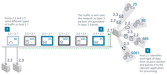
The first three layers of the OSI model are primarily concerned with moving frames and datagrams between nodes and networks. At the transport layer-also known as the end-to-end or host-to-host layer-the content of the packets becomes significant. Any given host on a network will be communicating with many other hosts using many different types of networking data. One of the functions of the transport layer is to identify each type of network application by assigning it a port number. For example, data requested from an HTTP web application can be identified as port 80, while data sent to an email server can be identified as port 25.
At the transport layer, on the sending host, data from the upper layers is packaged as a series of layer 4 PDUs, referred to as segments. Each segment is tagged with the application's port number. The segment is then passed to the network layer for delivery. Many different hosts could be transmitting multiple HTTP and email packets at the same time. These are multiplexed using the port numbers along with the source and destination network addresses onto the same link.
At the network and data link layers, the port number is ignored-it becomes part of the data payload and is invisible to the routers and switches that implement the addressing and forwarding functions of these layers. At the receiving host, each segment is decapsulated, identified by its port number, and passed to the relevant handler at the application layer. Put another way, the traffic stream is de-multiplexed.
The transport layer can also implement reliable data delivery mechanisms, should the application require it. Reliable delivery means that any lost or damaged packets are resent.
Devices working at the transport layer include multilayer switches-usually working as load balancers-and many types of security appliances, such as more advanced firewalls and intrusion detection systems (IDSs).
Upper Layers
The upper layers of the OSI model are less clearly associated with distinct real-world protocols. These layers collect various functions that provide useful interfaces between software applications and the transport layer.
Layer 5-Session
Most application protocols require the exchange of multiple messages between the client and server. This exchange of such a sequence of messages is called a session or dialog. The session layer (layer 5) represents functions that administer the process of establishing a dialog, managing data transfer, and then ending (or tearing down) the session.
Layer 6-Presentation
The presentation layer (layer 6) transforms data between the format required for the network and the format required for the application. For example, the presentation layer is used for character set conversion, such as between American Standard Code for Information Interchange (ASCII) and Unicode. The presentation layer can also be conceived as supporting data compression and encryption. However, in practical terms, these functions are often implemented by encryption devices and protocols running at lower layers of the stack or simply within a homogenous application layer.
Layer 7-Application
The application layer (layer 7) is at the top of the OSI stack. An application-layer protocol doesn't encapsulate any other protocols or provide services to any protocol. Application-layer protocols provide an interface for software programs on network hosts that have established a communications channel through the lower-level protocols to exchange data.
More widely, upper-layer protocols provide most of the services that make a network useful, rather than just functional, including web browsing, email and communications, directory lookup, remote printing, and database services.
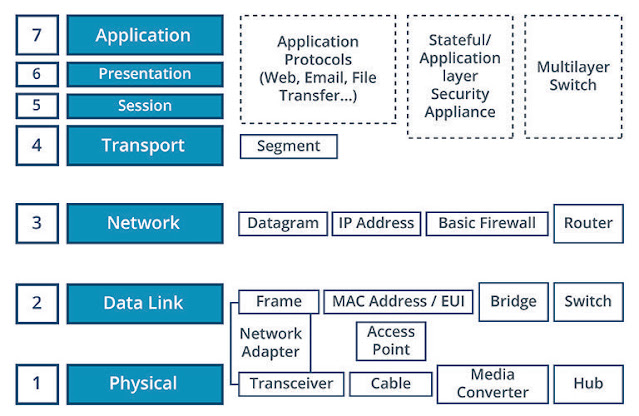
OSI Model Summary
The following image summarizes the OSI model, listing the PDUs at each layer, along with the types of devices that work at each layer.


Post a Comment for "Comparing OSI Model Network Functions"
Post a Comment